The seismic design category is a way of measuring the earthquake hazard in a given region. Buildings are assigned a Seismic Design Category (SDC) in accordance with their location on the map shown in IRC Figure R301.2(2). Note the following:
- Buildings in SDC A & B are in the lowest seismic hazard regions and are exempt from the seismic requirements of the IRC, as are detached one- and two-family dwellings in SDC C (see Section R301.2.2). For buildings in these regions this calculator will determine wind bracing amounts only.
- Buildings located in SDC E are in the highest seismic hazard regions and are not permitted to be designed using the IRC. The IRC and this calculator will not evaluate buildings in SDC E (see Section R301.2.2.4).
- The U.S. Geological Survey (USGS) offers a calculation tool to help determine the appropriate Seismic Design Category based on the project site zip code or longitude and latitude. Go to the USGS website at Design Ground Motions (usgs.gov) for more information.
- Contact the local building department to confirm the Seismic Design Category.
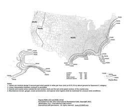
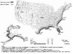
The Basic Wind Speed is a design parameter that represents a home's potential exposure to a hurricane, as determined by its location on the map in IRC Figure R301.2(4). Note the following:
- This calculator evaluates the wind speeds included in IRC Table R602.10.1.2(1):
85 mph < 110 mph. - Buildings located in regions where the basic wind speed equals or exceeds 100 mph in hurricane-prone regions (Atlantic and Gulf of Mexico coasts and several islands) or 110 mph elsewhere may not use the bracing provisions of the IRC (see Section R301.2.1.1). It is the user's responsibility to verify that IRC wind bracing provisions are acceptable where the basic wind speed equals or exceeds 100 mph.
- Contact the local building department to confirm the Basic Wind Speed.
Basic Wind Speed map
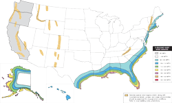
Click for larger version
The Wind Exposure Category reflects the characteristics of the ground surface surrounding the home. If the home is surrounded by several similar-sized objects, then the wind won't affect it as much as it would if the home were out in the open. The IRC defines the following exposure categories (see Section R301.2.1.4):
- Exposure B: Urban and suburban areas, wooded areas, or other terrain with numerous closely spaced obstructions having the size of single-family dwellings or larger. Exposure B shall be assumed unless the site meets the definition of another type exposure. The wind bracing amounts tabulated in the IRC are based on Exposure B.
- Exposure C: Open terrain with scattered obstructions, including surface undulations or other irregularities, having heights generally less than 30 feet extending more than 1,500 feet from the building site in any quadrant. This exposure shall also apply to any building located within Exposure B- type terrain where the building is directly adjacent to open areas of Exposure C-type terrain in any quadrant for a distance of more than 600 feet. This category includes flat open country, grasslands and shorelines in hurricane-prone regions. Bracing in Exposure C buildings will increase 20-40%.
- Exposure D: Flat, unobstructed areas exposed to wind flowing over open water (excluding shorelines in hurricane-prone regions) for a distance of at least 1 mile. Shorelines in Exposure D include inland waterways, the Great Lakes and coastal areas of California, Oregon, Washington and Alaska. This exposure shall apply only to those buildings and other structures exposed to the wind coming from over the water. Exposure D extends inland from the shoreline a distance of 1,500 feet or 10 times the height of the building or structure, whichever is greater. Buildings in Exposure D will have a 50-70% increase in bracing.
- Contact the local building department with questions about which exposure to assume.
A minimum of two braced-wall lines are required in a given direction. Additional braced-wall lines will reduce the spacing between braced-wall lines thereby greatly reducing the tabulated wind bracing amounts. To compensate, an adjustment factor must be applied to ensure the total amount of bracing in each direction is about the same for a given structure regardless of the number of braced-wall lines (see Table R602.10.1.2(1) footnote e). The seismic bracing amounts are not affected by the number of parallel braced-wall lines.
The 2012 IRC does not specify how to determine the spacing associated with a Braced Wall Line that has parallel braced wall lines on both sides. In reference to the figure shown here, some jurisdictions may require the spacing associated with BWL B to be the greater of the distance between A & B and B & C (34-ft). This matches the requirements in the 2009 IRC but is conservative for most cases. Some jurisdictions may permit the spacing associated with BWL B to be the average distance between A & B and B & C (28-ft), which typically results in a lower amount of required bracing.
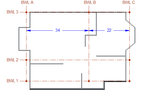
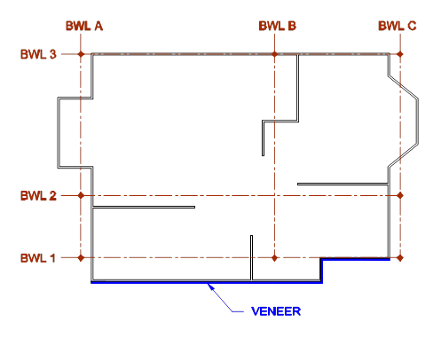
Section R602.10.6.5 of the 2012 IRC requires method BV-WSP on “exterior braced wall lines and braced wall lines on the interior of the building, backing or perpendicular to and laterally supporting veneered walls” when the stone or masonry veneer exceeds the first-story height of detached one-or two-family dwellings in SDC D0, D1, or D2. In reference to the figure shown here, Method BV-WSP must be used on BWLs 1, A, B, and C.
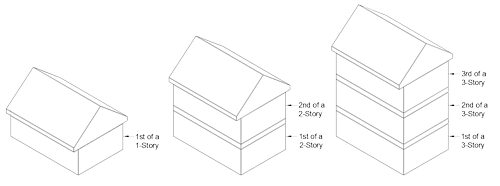
The required wind and seismic bracing amounts in the IRC are increased as the number of stories above the braced-wall line is increased (see Tables R602.10.1.2(1) and R602.10.1.2(2)).
In some cases the number of stories above the braced-wall lines will be different for braced-wall lines within the same story. One example would be a single-story attached garage that is fully outside the perimeter of a two-story residence.
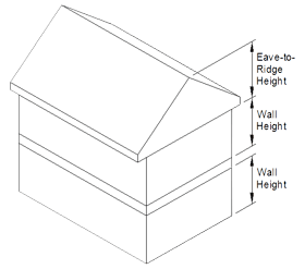
Height measured from the top of the wall to the top of the roof ridge. The tabulated bracing amounts in the IRC are based on a height of 10 feet. Increasing or decreasing the height will increase or decrease the wind bracing amounts by as much as -30% to +60% (see Table R602.10.1.2(1) footnote c). The seismic bracing amounts are not affected by the eave-to-ridge height.
In some cases, stone or masonry veneer that exceeds the 1st story level will increase the required amount of seismic bracing and/or add new bracing requirements (see Section R602.12). Wind bracing amounts are not affected by stone or masonry veneer. See Section R703.7 for additional information on stone and masonry veneer.
The tabulated seismic bracing amounts in the IRC are based on a 15 psf wall dead load. Dead loads of 8 psf or less will decrease the required seismic bracing amounts by 15% (see Table R602.10.1.2(3)). See Section R301.4 for determining dead loads.
A typical wood-stud partition wall with 1/2-inch gypsum board on both sides has an estimated dead load of 8 psf. A typical exterior wood-stud wall has an estimated dead load greater than 8 psf. See ASCE 7-05 standard and commentary for additional information.
Wind bracing amounts are not affected by wall dead load.
The tabulated seismic bracing amounts in the IRC are based on a 15 psf Roof/Ceiling Dead Load. Larger dead loads will increase the required seismic bracing amounts up to 20% (see Table R602.10.1.2(3)). See Section R301.4 for determining dead loads.
A typical asphalt shingle roof/ceiling assembly has an estimated dead load of 15 psf or less. Heavier roof coverings such as clay or concrete tile may result in a roof/ceiling dead load greater than 15 psf. See ASCE 7-05 standard and commentary for additional information.
Wind bracing amounts are not affected by roof/ceiling dead load.
The distance between adjacent, parallel braced-wall lines. The spacing for braced wall lines that have parallel braced-wall lines on both sides is the greater of the distance between each braced-wall line (see Figure R602.10.1.4(4)).
The maximum braced-wall-line spacing for all buildings in SDC A and B and detached one- or two-family dwellings in SDC C is 60 feet (see Table R602.10.1.2(1)). The maximum spacing for townhouses in SDC C is 50 feet (see Table R602.10.1.2(3)). The maximum spacing for all buildings in SDC D0, D1, and D2 is 25 feet with an exception that permits a single spacing up to 35 feet (see Section R602.10.1.5).
This calculator evaluates the parameters entered and limits the maximum spacing to 60, 50, or 35 feet on center and adjusts bracing amounts accordingly. For buildings in SDC D0, D1, and D2 the user must ensure Braced-Wall-Line Spacing greater than 25 feet is acceptable.
The distance between the ends of the braced-wall line. The end of a braced wall line is considered to be the maximum length resulting from: a) the intersection with perpendicular exterior walls or b) the intersection with perpendicular braced wall lines (see Section R602.10.1).
The longer a braced-wall line, the more mass that wall line must support. Seismic bracing amounts are increased linearly as braced-wall line length is increased. Wind bracing amounts are not affected by braced-wall line length.
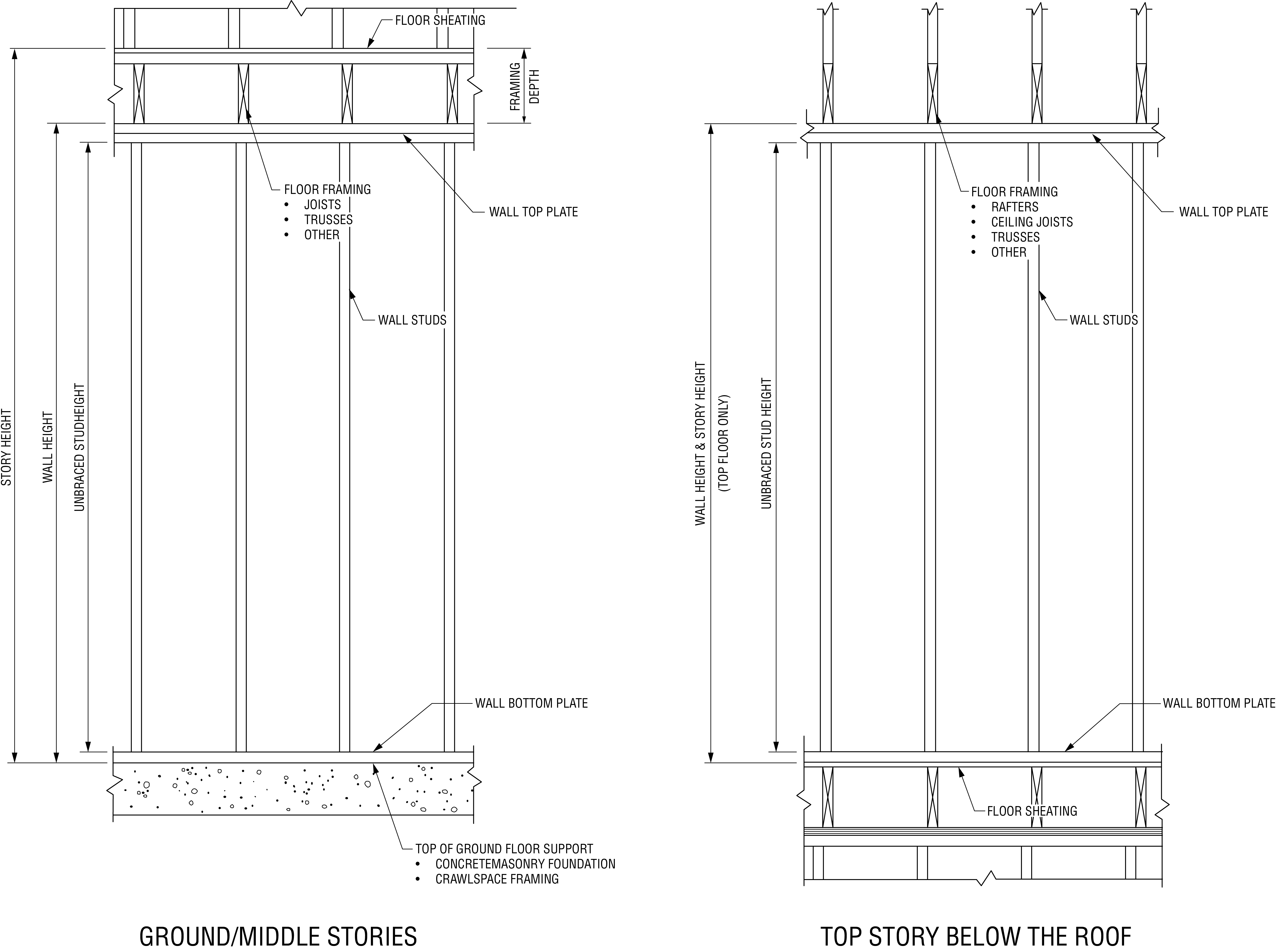
Wall height shall be the vertical distance from the lower edge of the bottom plate to the upper edge of the upper top plate.
As wall height is increased the wind surface area increases and the mass of the wall increases. The tabulated wind and seismic bracing amounts are based on a wall height of 10 feet. Shorter wall heights will reduce the required amount of wind bracing by up to 10%. Taller wall heights will increase the required amount of wind and seismic bracing by up to 20%. See Section R301.3, Table R602.10.1.2(1) footnote d, and Table R602.10.1.2(3) for more information.
The building codes define various construction methods that may be used to build a code-compliant braced wall panel:
- Let-In Bracing (LIB)
- Diagonal Wood Board (DWB)
- Wood-Structural-Panel Sheathing (WSP)
- Gypsum Board (GB)
- Structural Fiberboard Sheathing (SFB)
- Particleboard Sheathing (PBS)
- Portland Cement Plaster (PCP)
- Hardboard Panel Siding (HPS)
- Continuously Sheathed (CS)
The required amount of wind and seismic bracing is dependent on the method of wall bracing used. Generally, methods LIB (let-in-bracing) and GB (gypsum board) are considered the weakest, method CS (continuous sheathing) is considered the strongest, and the other methods are in between.
Eight intermittent methods and three narrow alternates are described in Table R602.10.2. Continuous sheathing methods are described in Table R602.10.4.1. Stone or masonry veneer exceeding the 1st story height in higher SDC regions requires wood structural panel sheathing and holdowns installed in accordance with Section R602.12.1.3 and is indicated in this calculator as method BV-WSP.
When mixing bracing methods, the user must ensure the following limits are satisfied (see Section R602.10.1.1):
- Mixing bracing methods from story to story is permitted.
- Mixing intermittent bracing methods from braced-wall line to braced-wall line is permitted.
- Mixing intermittent bracing methods within a single braced-wall line is permitted for all buildings in SDC A and B and detached one- or two-family dwellings in SDC C. The length of required bracing must be based on the highest amount required for each of the methods used in the braced-wall line.
- Mixing continuous sheathing methods and intermittent methods within a single braced wall line is not permitted (see R602.10.4).
- Mixing continuous sheathing methods with intermittent methods from exterior braced wall line to exterior braced-wall line is not permitted in SDC D0, D1, and D2 or in Basic Winds Speeds greater than 100 mph. This is permitted in other regions (see R602.10.4).
The required wind and seismic bracing amounts are based on braced wall panels with gypsum wall board on the side of the wall opposite the bracing material. Some bracing methods are exempted from this requirement, other methods are permitted to omit the gypsum wall board with increases in bracing amounts up to 80%, and other methods are permitted to omit the gypsum wall board without penalty (see Section R602.10.2.1). This calculator evaluates parameters entered such as bracing method and allows the user to enter yes or no only when permitted. The effect of omitting gypsum wall board is shown as the "Gypsum on Inside Factor" in the Wind and Seismic calculation summary.
The required wind and seismic bracing amounts for Method GB bracing are based on double-sided gypsum wall board. Single-sided gypsum wall board doubles the required bracing amounts (see Table R602.10.1.2(1) footnote g for wind, and Section R602.10.3 for seismic).
Gypsum wall board panels installed horizontally will not require blocking of horizontal joints (see Section R602.10.8) excepted as noted below.
The required wind bracing amount for Method GB may be reduced by 30% when double-sided GB is installed with blocked horizontal joints and fastened at 4 inches on center at all panel edges (see Table R602.10.1.2(1) footnote g).
Bracing methods that use sheathing panels must have blocking behind all horizontal joints. Some bracing methods permit the blocking to be omitted when the wind and seismic bracing amounts are doubled; others permit blocking to be omitted without penalty (see Section R602.10.8). This calculator allows the user to enter yes or no only when omitting the blocking is permitted by the bracing method. The effect of omitting blocking is shown as the "Blocked Joint Factor" in the Wind and Seismic calculation summary.
The required wind bracing amount may be reduced by 20% for some methods when an 800-pound holdown device is used on the end studs of each braced-wall panel in the braced-wall line (see Table R602.10.1.2(1) footnote i).
Stone or masonry veneer exceeding the first-story height in higher SDC regions requires wood structural panel sheathing and holdowns installed in accordance with Section R602.12.1.3 and is indicated in this calculator as method BV-WSP. When method BV-WSP is required, "Holdown Device Used" defaults to "Yes."
Click to save a file containing this project's information, which can be imported back to this calculator at a later time.
The seismic design category is a way of measuring the earthquake hazard in a given region. Buildings are assigned a Seismic Design Category (SDC) in accordance with their location on the map shown in IRC Figure R301.2(2). Note the following:
- Buildings in SDC A & B are in the lowest seismic hazard regions and are exempt from the seismic requirements of the IRC, as are detached one- and two-family dwellings in SDC C (see Section R301.2.2). For buildings in these regions this calculator will determine wind bracing amounts only.
- Buildings located in SDC E are in the highest seismic hazard regions and are not permitted to be designed using the IRC. The IRC and this calculator will not evaluate buildings in SDC E (see Section R301.2.2.4).
- The U.S. Geological Survey (USGS) offers a calculation tool to help determine the appropriate Seismic Design Category based on the project site zip code or longitude and latitude. Go to the USGS website at Design Ground Motions (usgs.gov) for more information.
- Contact the local building department to confirm the Seismic Design Category.
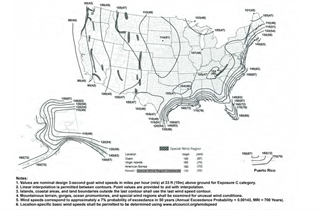
The Basic Wind Speed is a design parameter that represents a home's potential exposure to high winds, as determined by its location on the map in IRC Figure R301.2(4)A. Note the following:
- This calculator evaluates the wind speeds included in IRC Table R602.10.3.1:
85 mph–110 mph. - Buildings located in regions where the basic wind speed equals or exceeds 110 mph from Figure R301.2(4)A or where wind design is required in accordance with Figure R301.2(4)B may not use the bracing provisions of the IRC (see Section R301.2.1.1).
- Contact the local building department to confirm the Basic Wind Speed.
Basic Wind Speed map
Click for larger version
The Wind Exposure Category reflects the characteristics of the ground surface surrounding the home. If the home is surrounded by several similar-sized objects, then the wind won't affect it as much as it would if the home were out in the open. The IRC defines the following exposure categories (see Section R301.2.1.4):
- Exposure B: Urban and suburban areas, wooded areas, or other terrain with numerous closely spaced obstructions having the size of single-family dwellings or larger. Exposure B shall be assumed unless the site meets the definition of another type exposure. The wind bracing amounts tabulated in the IRC are based on Exposure B.
- Exposure C: Open terrain with scattered obstructions, including surface undulations or other irregularities, having heights generally less than 30 feet extending more than 1,500 feet from the building site in any quadrant. This exposure shall also apply to any building located within Exposure B- type terrain where the building is directly adjacent to open areas of Exposure C-type terrain in any quadrant for a distance of more than 600 feet. This category includes flat open country and grasslands. Bracing in Exposure C buildings will increase 20-40% over Exposure B amounts.
- Exposure D: Flat, unobstructed areas exposed to wind flowing over open water for a distance of at least 1 mile. Shorelines in Exposure D include inland waterways, the Great Lakes and coastal areas of California, Oregon, Washington and Alaska. This exposure shall apply only to those buildings and other structures exposed to the wind coming from over the water. Exposure D extends inland from the shoreline a distance of 1,500 feet or 10 times the height of the building or structure, whichever is greater. Buildings in Exposure D will have a 50-70% increase in bracing over Exposure B amounts.
- Contact the local building department with questions about which exposure to assume.
A minimum of two braced-wall lines are required in a given direction. Additional braced-wall lines will reduce the spacing between braced-wall lines thereby reducing the tabulated wind bracing amounts on each wall line. To compensate, an adjustment factor must be applied to ensure the total amount of bracing in each direction is about the same for a given structure regardless of the number of braced-wall lines (see Table R602.10.3(2)). The seismic bracing amounts are not affected by the number of parallel braced-wall lines.
The 2012 IRC does not specify how to determine the spacing associated with a Braced Wall Line that has parallel braced wall lines on both sides. In reference to the figure shown here, some jurisdictions may require the spacing associated with BWL B to be the greater of the distance between A & B and B & C (34-ft). This matches the requirements in the 2009 IRC but is conservative for most cases. Some jurisdictions may permit the spacing associated with BWL B to be the average distance between A & B and B & C (28-ft), which typically results in a lower amount of required bracing.
Section R602.10.6.5 of the 2012 IRC requires method BV-WSP on “exterior braced wall lines and braced wall lines on the interior of the building, backing or perpendicular to and laterally supporting veneered walls” when the stone or masonry veneer exceeds the first-story height of detached one-or two-family dwellings in SDC D0, D1, or D2. In reference to the figure shown here, Method BV-WSP must be used on BWLs 1, A, B, and C.
The required wind and seismic bracing amounts in the IRC are increased as the number of stories above the braced-wall line is increased (see Tables R602.10.1.3(1) and R602.10.1.3(3)).
In some cases the number of stories above the braced-wall lines will be different for braced-wall lines within the same story. One example would be a single-story attached garage that is fully outside the perimeter of a two-story residence.
Height measured from the top of the wall to the top of the roof ridge. The tabulated wind bracing amounts in the IRC are based on a height of 10 feet. Increasing or decreasing the height will increase or decrease the wind bracing amounts by as much as +60% to -30% (see Table R602.10.3(2)). The seismic bracing amounts are not affected by the eave-to-ridge height.
In some cases, stone or masonry veneer that exceeds the 1st story level will increase the required amount of seismic bracing and/or add new bracing requirements (see Section R602.10.6.5). Wind bracing amounts are not affected by stone or masonry veneer. See Section R703.7 for additional information on stone and masonry veneer.
The tabulated seismic bracing amounts in the IRC are based on a 15 psf wall dead load. Dead loads of 8 psf or less will decrease the required seismic bracing amounts by 15% (see Table R602.10.3(4)). See Section R301.4 for determining dead loads.
A typical wood-stud partition wall with 1/2-inch gypsum board on both sides has an estimated dead load of 8 psf. A typical exterior wood-stud wall has an estimated dead load greater than 8 psf. See ASCE 7-05 standard and commentary for additional information.
Wind bracing amounts are not affected by wall dead load.
The tabulated seismic bracing amounts in the IRC are based on a 15 psf Roof/Ceiling Dead Load. Larger dead loads will increase the required seismic bracing amounts up to 20% (see Table R602.10.3(4)). See Section R301.4 for determining dead loads.
A typical asphalt shingle roof/ceiling assembly has an estimated dead load of 15 psf or less. Heavier roof coverings such as clay or concrete tile may result in a roof/ceiling dead load greater than 15 psf. See ASCE 7-05 standard and commentary for additional information.
Wind bracing amounts are not affected by roof/ceiling dead load.
The distance between adjacent, parallel braced-wall lines. The spacing for braced wall lines that have parallel braced-wall lines on both sides is the greater of the distance between each braced-wall line (see Figure R602.10.1.1).
The maximum braced wall line spacing for all buildings in SDC A and B and detached one- or two-family dwellings in SDC C is 60 feet and the maximum spacing for townhouses in SDC C is 50 feet (see Table R602.10.1.3). The maximum spacing for all buildings in SDC D0, D1, and D2 is 25 feet with an exception that permits a single spacing up to 35 feet (see Table R602.10.1.3).
This calculator evaluates the parameters entered and limits the maximum spacing to 60, 50, or 35 feet on center and adjusts bracing amounts accordingly. For buildings in SDC D0, D1, and D2 the user must ensure Braced Wall Line Spacing greater than 25 feet is acceptable.
The length of a braced wall line is the distance between the ends of the braced-wall line. The end of a braced wall line is either : a) the intersection with perpendicular exterior walls or b) the intersection with perpendicular or angled braced wall lines (see Section R602.10.1.1).
The longer a braced-wall line, the more mass that wall line must support. Seismic bracing amounts are increased linearly as braced-wall line length is increased. Wind bracing amounts are not affected by braced-wall line length.
Wall height shall be the vertical distance from the lower edge of the bottom plate to the upper edge of the upper top plate.
As wall height is increased the wind surface area increases and the mass of the wall increases. The tabulated wind and seismic bracing amounts are based on a wall height of 10 feet. Shorter wall heights will reduce the required amount of wind bracing by up to 10%. Taller wall heights will increase the required amount of wind and seismic bracing by up to 20%. See Section R301.3, Tables R602.10.3(2) and R602.10.3(4) for more information.
The building codes define various construction methods that may be used to build a code-compliant braced wall panel:
- Let-In Bracing (LIB)
- Diagonal Wood Board (DWB)
- Wood-Structural-Panel Sheathing (WSP)
- Gypsum Board (GB)
- Structural Fiberboard Sheathing (SFB)
- Particleboard Sheathing (PBS)
- Portland Cement Plaster (PCP)
- Hardboard Panel Siding (HPS)
- Continuously Sheathed (CS)
- Alternate Braced Wall (ABW)
- Wood Structural Panels with Stone or Masonry Veneer (BV-WSP)
- Continuously sheathed structural fiberboard (CS-SFB)
The required amount of wind and seismic bracing is dependent on the method of wall bracing used. Generally, methods LIB (let-in-bracing) and GB (gypsum board) are considered the weakest, method CS (continuous sheathing) is considered the strongest, and the other methods are in between.
Twelve intermittent methods and four continuous sheathing methods are described in Table R602.10.4. Stone or masonry veneer exceeding the 1st story height in higher SDC regions requires wood structural panel sheathing and holdowns installed in accordance with Section R602.10.6.5 and is indicated in this calculator as method BV-WSP.
When mixing bracing methods, the user must ensure the following limits are satisfied (see Section R602.10.4.1):
- Mixing intermittent and continuous sheathing bracing methods from story to story is permitted.
- Mixing intermittent bracing methods from braced-wall line to braced-wall line within a story is permitted. Within Seismic Design Categories A, B and C or in regions where the basic wind speed is less than or equal to 100 mph, mixing of intermittent bracing and continuous sheathing methods from braced wall line to braced wall line within a story shall be permitted.
- Mixing intermittent bracing methods along a braced-wall line is permitted for all buildings in SDC A and B and dwellings in SDC C provided the length of required bracing in accordance with Table R602.10.3(1) or R602.10.3(3) is the highest value of all intermittent bracing methods used.
- Mixing continuous sheathing methods CS-WSP, CS-G and CS-PF along a braced wall line shall be permitted.
- Mixing continuous sheathing methods with intermittent methods from exterior braced wall line to exterior braced-wall line is not permitted in SDC D0, D1, and D2 or in Basic Winds Speeds greater than 100 mph. This is permitted in other regions (see R602.10.4).
- In Seismic Design Categories A and B, and for detached one- and two- family dwellings in Seismic Design Category C, mixing of intermittent bracing methods along the interior portion of a braced wall line with continuous sheathing methods CS-WSP, CS-G and CS-PF along the exterior portion of the same braced wall line shall be permitted. The length of required bracing shall be the highest value of all intermittent bracing methods used in accordance with Table R602.10.3(1) or R602.10.3(3) as adjusted by Tables R602.10.3(2) and R602.10.3(4), respectively. The requirements of Section R602.10.7 shall apply to each end of the continuously sheathed portion of the braced wall line.
The required wind and seismic bracing amounts are based on braced wall panels with gypsum wall board on the side of the wall opposite the bracing material. Some bracing methods are exempted from this requirement, other methods are permitted to omit the gypsum wall board with increases in bracing amounts up to 50%, and other methods are permitted to omit the gypsum wall board without penalty (see Tables R602.10.3(2) and R602.10.3(4)). This calculator evaluates parameters entered such as bracing method and allows the user to enter yes or no only when permitted. The effect of omitting gypsum wall board is shown as the "Gypsum on Inside Factor" in the Wind and Seismic calculation summary.
The required wind and seismic bracing amounts for Method GB bracing are based on double-sided gypsum wall board. Single-sided gypsum wall board doubles the required bracing amounts (see Table R602.10.5).
Gypsum wall board panels installed horizontally will not require blocking of horizontal joints (see Section R602.10.10) excepted as noted below.
The required wind bracing amount for Method GB may be reduced by 30% when double-sided GB is installed with blocked horizontal joints and fastened at 4 inches on center at all panel edges (see Table R602.10.3(2)).
Bracing methods that use sheathing panels must have blocking behind all horizontal joints. Some bracing methods permit the blocking to be omitted when the wind and seismic bracing amounts are doubled, others permit blocking to be omitted without penalty (see Section R602.10.10). This calculator allows the user to enter yes or no only when omitting the blocking is permitted by the bracing method. The effect of omitting blocking is shown as the "Blocked Joint Factor" in the Wind and Seismic calculation summary.
The required wind bracing amount may be reduced by 20% for some methods when an 800-pound holdown device is used on the end studs of each braced-wall panel in the braced-wall line (see Table R602.10.3(2)).
Stone or masonry veneer exceeding the first-story height in higher SDC regions requires wood structural panel sheathing and holdowns installed in accordance with Section R602.10.6.5 and is indicated in this calculator as method BV-WSP. When method BV-WSP is required, "Holdown Device Used" defaults to "Yes."
The seismic design category is a way of measuring the earthquake hazard in a given region. Buildings are assigned a Seismic Design Category (SDC) in accordance with their location on the map shown in IRC Figure R301.2(2). Note the following:
- Buildings in SDC A & B are in the lowest seismic hazard regions and are exempt from the seismic requirements of the IRC, as are detached one- and two-family dwellings in SDC C (see Section R301.2.2). For buildings in these regions this calculator will determine wind bracing amounts only.
- Buildings located in SDC E are in the highest seismic hazard regions and are not permitted to be designed using the IRC. The IRC and this calculator will not evaluate buildings in SDC E (see Section R301.2.2.4).
- The U.S. Geological Survey (USGS) offers a calculation tool to help determine the appropriate Seismic Design Category based on the project site zip code or longitude and latitude. Go to the USGS website at Design Ground Motions (usgs.gov) for more information.
- Contact the local building department to confirm the Seismic Design Category.
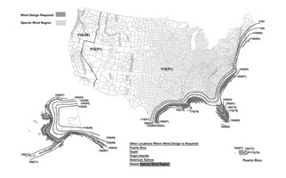
The Ultimate Design Wind Speed is a design parameter that represents a home's potential exposure to high winds, as determined by its location on the map in IRC Figure R301.2(4)A. Note the following:
- This calculator evaluates the wind speeds included in IRC Table R602.10.3.1:
110 mph–140 mph. - Buildings located in regions where the ultimate design wind speed equals or exceeds 140 mph from Figure R301.2(4)A or where wind design is required in accordance with Figure R301.2(4)B may not use the bracing provisions of the IRC (see Section R301.2.1.1).
- Contact the local building department to confirm the Ultimate Design Wind Speed.
Ultimate Design Wind Speed map
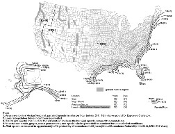
Click for larger version
The Wind Exposure Category reflects the characteristics of the ground surface surrounding the home. If the home is surrounded by several similar-sized objects, then the wind won't affect it as much as it would if the home were out in the open. The IRC defines the following exposure categories (see Section R301.2.1.4):
- Exposure B: Urban and suburban areas, wooded areas, or other terrain with numerous closely spaced obstructions having the size of single-family dwellings or larger. Exposure B shall be assumed unless the site meets the definition of another type exposure. The wind bracing amounts tabulated in the IRC are based on Exposure B.
- Exposure C: Open terrain with scattered obstructions, including surface undulations or other irregularities, having heights generally less than 30 feet extending more than 1,500 feet from the building site in any quadrant. This exposure shall also apply to any building located within Exposure B type terrain where the building is directly adjacent to open areas of Exposure C type terrain in any quadrant for a distance of more than 600 feet. This category includes flat, open country and grasslands. Bracing in Exposure C buildings will increase 20-40% over Exposure B amounts.
- Exposure D: Flat, unobstructed areas exposed to wind flowing over open water, smooth mud flats, salt flats and unbroken ice for a distance of not less than 5,000 feet. This exposure shall apply only to those buildings and other structures exposed to the wind coming from over the unobstructed area. Exposure D extends downwind from the edge of the unobstructed area a distance of 600 feet or 20 times the height of the building or structure, whichever is greater. Buildings in Exposure D will have a 50-70% increase in bracing over Exposure B amounts.
- Contact the local building department with questions about which exposure to assume.
In some cases, stone or masonry veneer that exceeds the 1st story level will increase the required amount of seismic bracing and/or add new bracing requirements (see Section R602.10.6.5). Wind bracing amounts are not affected by stone or masonry veneer. See Section R703.7 for additional information on stone and masonry veneer.
A minimum of two braced-wall lines are required in a given direction. Additional braced-wall lines will reduce the spacing between braced-wall lines thereby reducing the tabulated wind bracing amounts on each wall line. To compensate, an adjustment factor must be applied to ensure the total amount of bracing in each direction is about the same for a given structure regardless of the number of braced-wall lines (see Table R602.10.3(2)). The seismic bracing amounts are not affected by the number of parallel braced-wall lines.
The distance between adjacent, parallel braced-wall lines. The spacing for braced wall lines that have parallel braced-wall lines on both sides is the greater of the distance between each braced-wall line (see Figure R602.10.1.1).
The maximum braced wall line spacing for all buildings in SDC A and B and detached one- or two-family dwellings in SDC C is 60 feet and the maximum spacing for townhouses in SDC C is 50 feet (see Table R602.10.1.3). The maximum spacing for all buildings in SDC D0, D1, and D2 is 25 feet with an exception that permits a single spacing up to 35 feet (see Table R602.10.1.3).
This calculator evaluates the parameters entered and limits the maximum spacing to 60, 50, or 35 feet on center and adjusts bracing amounts accordingly. For buildings in SDC D0, D1, and D2 the user must ensure Braced Wall Line Spacing greater than 25 feet is acceptable.
The 2021 IRC includes two options to determine the spacing associated with a Braced Wall Line that has parallel braced wall lines on both sides. In reference to the figure shown here, the spacing associated with BWL B may be taken as the greater of the distance between A & B and B & C (34-ft). Alternatively, the spacing associated with BWL B may be taken as the average distance between A & B and B & C (28-ft), which typically results in a lower amount of required bracing (see Table R602.10.3(1) Footnote c).
The required wind and seismic bracing amounts in the IRC are increased as the number of stories above the braced-wall line is increased (see Tables R602.10.3(1) and R602.10.3(3)).
In some cases the number of stories above the braced-wall lines will be different for braced-wall lines within the same story. One example would be a single-story attached garage that is fully outside the perimeter of a two-story residence.
Height measured from the top of the wall to the top of the roof ridge. The tabulated wind bracing amounts in the IRC are based on a height of 10 feet. Increasing or decreasing the height will increase or decrease the wind bracing amounts by as much as +60% to -30% (see Table R602.10.3(2)). The seismic bracing amounts are not affected by the eave-to-ridge height.
Wall height shall be the vertical distance from the lower edge of the bottom plate to the upper edge of the upper top plate.
As wall height is increased the wind surface area increases and the mass of the wall increases. The tabulated wind and seismic bracing amounts are based on a wall height of 10 feet. Shorter wall heights will reduce the required amount of wind bracing by up to 10%. Taller wall heights will increase the required amount of wind and seismic bracing by up to 20%. See Section R301.3, Tables R602.10.3(2) and R602.10.3(4) for more information.
The building codes define various construction methods that may be used to build a code-compliant braced wall panel:
- Let-In Bracing (LIB)
- Diagonal Wood Board (DWB)
- Wood-Structural-Panel Sheathing (WSP)
- Gypsum Board (GB)
- Structural Fiberboard Sheathing (SFB)
- Particleboard Sheathing (PBS)
- Portland Cement Plaster (PCP)
- Hardboard Panel Siding (HPS)
- Continuously Sheathed (CS)
- Alternate Braced Wall (ABW)
- Wood Structural Panels with Stone or Masonry Veneer (BV-WSP)
- Continuously sheathed structural fiberboard (CS-SFB)
The required amount of wind and seismic bracing is dependent on the method of wall bracing used. Generally, methods LIB (let-in-bracing) and GB (gypsum board) are considered the weakest, method CS (continuous sheathing) is considered the strongest, and the other methods are in between.
Twelve intermittent methods and four continuous sheathing methods are described in Table R602.10.4. Stone or masonry veneer exceeding the 1st story height in higher SDC regions requires wood structural panel sheathing and holdowns installed in accordance with Section R602.10.6.5 and is indicated in this calculator as method BV-WSP.
When mixing bracing methods, the user must ensure the following limits are satisfied (see Section R602.10.4.1):
- Mixing intermittent and continuous sheathing bracing methods from story to story is permitted.
- Mixing intermittent bracing methods from braced-wall line to braced-wall line within a story is permitted. Within Seismic Design Categories A, B and C or in regions where the ultimate design wind speed is less than or equal to 130 mph, mixing of intermittent bracing and continuous sheathing methods from braced wall line to braced wall line within a story shall be permitted.
- Mixing intermittent bracing methods along a braced-wall line is permitted for all buildings in SDC A and B and detached dwellings in SDC C provided the length of required bracing in accordance with Table R602.10.3(1) or R602.10.3(3) is the highest value of all intermittent bracing methods used.
- Mixing continuous sheathing methods CS-WSP, CS-G and CS-PF along a braced wall line shall be permitted. Intermittent methods ABW, PFH and PFG shall be permitted to be used along a braced-wall line with continuous sheathed methods.
- Mixing continuous sheathing methods with intermittent methods from exterior braced wall line to exterior braced-wall line is not permitted in SDC D0, D1, and D2 or when ultimate design wind speed exceeds 130 mph. This is permitted in other regions (see R602.10.4).
- In Seismic Design Categories A and B, and for detached one- and two- family dwellings in Seismic Design Category C, mixing of intermittent bracing methods along the interior portion of a braced wall line with continuous sheathing methods CS-WSP, CS-G and CS-PF along the exterior portion of the same braced wall line shall be permitted. The length of required bracing shall be the highest value of all intermittent bracing methods used in accordance with Table R602.10.3(1) or R602.10.3(3) as adjusted by Tables R602.10.3(2) and R602.10.3(4), respectively. The requirements of Section R602.10.7 shall apply to each end of the continuously sheathed portion of the braced wall line.
The required wind and seismic bracing amounts are based on braced wall panels with gypsum wall board on the side of the wall opposite the bracing material. Some bracing methods are exempted from this requirement, other methods are permitted to omit the gypsum wall board with increases in bracing amounts up to 50%, and other methods are permitted to omit the gypsum wall board without penalty (see Tables R602.10.3(2) and R602.10.3(4)). This calculator evaluates parameters entered such as bracing method and allows the user to enter yes or no only when permitted. The effect of omitting gypsum wall board is shown as the "Gypsum on Inside Factor" in the Wind and Seismic calculation summary
The required wind and seismic bracing amounts for Method GB bracing are based on double-sided gypsum wall board. Single-sided gypsum wall board doubles the required bracing amounts (see Table R602.10.5).
Gypsum wall board panels installed horizontally will not require blocking of horizontal joints (see Section R602.10.10) excepted as noted below.
The required wind bracing amount for Method GB may be reduced by 30% when double-sided GB is installed with blocked horizontal joints and fastened at 4 inches on center at all panel edges (see Table R602.10.3(2)).
Bracing methods that use sheathing panels must have blocking behind all horizontal joints. Some bracing methods permit the blocking to be omitted when the wind and seismic bracing amounts are doubled, others permit blocking to be omitted without penalty (see Section R602.10.10). This calculator allows the user to enter yes or no only when omitting the blocking is permitted by the bracing method. The effect of omitting blocking is shown as the "Blocked Joint Factor" in the Wind and Seismic calculation summary.
Bracing methods that use sheathing panels must have blocking behind all horizontal joints. Bracing methods WSP and CS-WSP permit the blocking to be omitted when the wind and seismic bracing amounts are doubled; methods SFB, PBS, HPS and CS-SFB require the horizontal joints to be blocked in all cases (see Section R602.10.4.4). This calculator allows the user to enter yes or no only when omitting the blocking is permitted by the bracing method. The effect of omitting blocking is shown as the "Blocked Joint Factor" in the Wind and Seismic calculation summary.
Bracing methods that use sheathing panels must have blocking behind all horizontal joints. Bracing methods WSP, CSP-WSP and PBS permit the blocking to be omitted when the wind and seismic bracing amounts are doubled; methods SFB, HPS and CS-SFB require the horizontal joints to be blocked in all cases (see Section R602.10.4.4). This calculator allows the user to enter yes or no only when omitting the blocking is permitted by the bracing method. The effect of omitting blocking is shown as the "Blocked Joint Factor" in the Wind and Seismic calculation summary.
The required wind bracing amount may be reduced by 20% for some methods when an 800-pound holdown device is used on the end studs of each braced-wall panel in the braced-wall line (see Table R602.10.3(2)).
Stone or masonry veneer exceeding the first-story height in higher SDC regions requires wood structural panel sheathing and holdowns installed in accordance with Section R602.10.6.5 and is indicated in this calculator as method BV-WSP. When method BV-WSP is required, "Holdown Device Used" defaults to "Yes."
Section R602.10.6.5 of the 2021 IRC requires method BV-WSP on "exterior braced wall lines and braced wall lines on the interior of the building, backing or perpendicular to and laterally supporting veneered walls" when the stone or masonry veneer exceeds the first-story height of detached one-or two-family dwellings in SDC D0, D1, or D2. In reference to the figure shown here, Method BV-WSP must be used on BWLs 1, A, B, and C.
The tabulated seismic bracing amounts in the IRC are based on a 15 psf wall dead load. Dead loads of 8 psf or less will decrease the required seismic bracing amounts by 15% (see Table R602.10.3(4)). See Section R301.4 for determining dead loads.
A typical wood-stud partition wall with 1/2-inch gypsum board on both sides has an estimated dead load of 8 psf. A typical exterior wood-stud wall has an estimated dead load greater than 8 psf. See ASCE 7-10 standard and commentary for additional information.
Wind bracing amounts are not affected by wall dead load.
The tabulated seismic bracing amounts in the IRC are based on a 15 psf Roof/Ceiling Dead Load. Larger dead loads will increase the required seismic bracing amounts up to 20% (see Table R602.10.3(4)). See Section R301.4 for determining dead loads.
A typical asphalt shingle roof/ceiling assembly has an estimated dead load of 15 psf or less. Heavier roof coverings such as clay or concrete tile may result in a roof/ceiling dead load greater than 15 psf. See ASCE 7-16 standard and commentary for additional information.
Wind bracing amounts are not affected by roof/ceiling dead load.
The length of a braced wall line is the distance between the ends of the braced-wall line. The end of a braced wall line is either : a) the intersection with perpendicular exterior walls or b) the intersection with perpendicular or angled braced wall lines (see Section R602.10.1.1).
The longer a braced-wall line, the more mass that wall line must support. Seismic bracing amounts are increased linearly as braced-wall line length is increased. Wind bracing amounts are not affected by braced-wall line length.
The seismic design category is a way of measuring the earthquake hazard in a given region. Buildings are assigned a Seismic Design Category (SDC) in accordance with their location on the map shown in IRC Figure R301.2(2). Note the following:
- Buildings in SDC A & B are in the lowest seismic hazard regions and are exempt from the seismic requirements of the IRC, as are detached one- and two-family dwellings in SDC C (see Section R301.2.2). For buildings in these regions this calculator will determine wind bracing amounts only.
- Buildings located in SDC E are in the highest seismic hazard regions and are not permitted to be designed using the IRC. The IRC and this calculator will not evaluate buildings in SDC E (see Section R301.2.2).
- Contact the local building department to confirm the Seismic Design Category.
The Ultimate Design Wind Speed is a design parameter that represents a home's potential exposure to high winds, as determined by its location on the map in IRC Figure R301.2(5)A. Note the following:
- This calculator evaluates the wind speeds included in IRC Table R602.10.3(1)
110 mph–140 mph. - Buildings located in regions where the ultimate design wind speed equals or exceeds 140 mph from Figure R301.2(5)A or where wind design is required in accordance with Figure R301.2(5)B may not use the bracing provisions of the IRC (see Section R301.2.1.1).
- Contact the local building department to confirm the Ultimate Design Wind Speed.
Ultimate Design Wind Speed map
Click for larger version
The building codes define various construction methods that may be used to build a code-compliant braced wall panel:
- Let-In Bracing (LIB)
- Diagonal Wood Board (DWB)
- Wood-Structural-Panel Sheathing (WSP)
- Gypsum Board (GB)
- Structural Fiberboard Sheathing (SFB)
- Particleboard Sheathing (PBS)
- Portland Cement Plaster (PCP)
- Hardboard Panel Siding (HPS)
- Continuously sheathed wood structural panel (CS-WSP)
- Continuously Sheathed (CS)
- Alternate Braced Wall (ABW)
- Wood Structural Panels with Stone or Masonry Veneer (BV-WSP)
- Continuously sheathed structural fiberboard (CS-SFB)
The required amount of wind and seismic bracing is dependent on the method of wall bracing used. Generally, methods LIB (let-in-bracing) and GB (gypsum board) are considered the weakest, method CS (continuous sheathing) is considered the strongest, and the other methods are in between.
Twelve intermittent methods and four continuous sheathing methods are described in Table R602.10.4. Stone or masonry veneer exceeding the 1st story height in higher SDC regions requires wood structural panel sheathing and holdowns installed in accordance with Section R602.10.6.5 and is indicated in this calculator as method BV-WSP.
When mixing bracing methods, the user must ensure the following limits are satisfied (see Section R602.10.4.1):
- Mixing intermittent and continuous sheathing bracing methods from story to story is permitted.
- Mixing intermittent bracing methods from braced-wall line to braced-wall line within a story is permitted. Within Seismic Design Categories A, B and C or in regions where the ultimate design wind speed is less than or equal to 130 mph, mixing of intermittent bracing and continuous sheathing methods from braced wall line to braced wall line within a story shall be permitted.
- Mixing intermittent bracing methods along a braced-wall line is permitted for all buildings in SDC A and B and detached dwellings in SDC C provided the length of required bracing in accordance with Table R602.10.3(1) or R602.10.3(3) is the highest value of all intermittent bracing methods used.
- Mixing continuous sheathing methods CS-WSP, CS-G and CS-PF along a braced wall line shall be permitted. Intermittent methods ABW, PFH and PFG shall be permitted to be used along a braced-wall line with continuous sheathed methods.
- Mixing continuous sheathing methods with intermittent methods from exterior braced wall line to exterior braced-wall line is not permitted in SDC D0, D1, and D2 or when ultimate design wind speed exceeds 130 mph. This is permitted in other regions (see R602.10.4).
- In Seismic Design Categories A and B, and for detached one- and two- family dwellings in Seismic Design Category C, mixing of intermittent bracing methods along the interior portion of a braced wall line with continuous sheathing methods CS-WSP, CS-G and CS-PF along the exterior portion of the same braced wall line shall be permitted. The length of required bracing shall be the highest value of all intermittent bracing methods used in accordance with Table R602.10.3(1) or R602.10.3(3) as adjusted by Tables R602.10.3(2) and R602.10.3(4), respectively. The requirements of Section R602.10.7 shall apply to each end of the continuously sheathed portion of the braced wall line.
In some cases, stone or masonry veneer that exceeds the 1st story level will increase the required amount of seismic bracing and/or add new bracing requirements (see Section R602.10.6.5). Wind bracing amounts are not affected by stone or masonry veneer. See Section R703.8 for additional information on stone and masonry veneer.
The tabulated seismic bracing amounts in the IRC are based on a 15 psf wall dead load. Dead loads of 8 psf or less will decrease the required seismic bracing amounts by 15% (see Table R602.10.3(4)). See Section R301.4 for determining dead loads.
A typical wood-stud partition wall with 1/2-inch gypsum board on both sides has an estimated dead load of 8 psf. A typical exterior wood-stud wall has an estimated dead load greater than 8 psf. See ASCE 7-16 standard and commentary for additional information.
Wind bracing amounts are not affected by wall dead load.
The required wind and seismic bracing amounts for Method GB bracing are based on double-sided gypsum wall board. Single-sided gypsum wall board doubles the required bracing amounts (see Table R602.10.5).
Gypsum wall board panels installed horizontally will not require blocking of horizontal joints (see Section R602.10.4.4) except as noted below.
The required wind bracing amount for Method GB may be reduced by 30% when double-sided GB is installed with blocked horizontal joints and fastened at 4 inches on center at all panel edges (see Table R602.10.3(2)).
The seismic design category is a way of measuring the earthquake hazard in a given region. Buildings are assigned a Seismic Design Category (SDC) in accordance with their location on the map shown in IRC Figure R301.2.2.1(1) through R301.2.2.1(6). Note the following:
- Buildings in SDC A & B are in the lowest seismic hazard regions and are exempt from the seismic requirements of the IRC, as are detached one- and two-family dwellings in SDC C (see Section R301.2.2). For buildings in these regions this calculator will determine wind bracing amounts only.
- Buildings located in SDC E are in the highest seismic hazard regions and are not permitted to be designed using the IRC. The IRC and this calculator will not evaluate buildings in SDC E (see Section R301.2.2).
- Contact the local building department to confirm the Seismic Design Category.
The Ultimate Design Wind Speed is a design parameter that represents a home's potential exposure to high winds, as determined by its location on the map in IRC Figure R301.2(2). Note the following:
- This calculator evaluates the wind speeds included in IRC Table R602.10.3(1)
95 mph–140 mph. - Buildings located in regions where the ultimate design wind speed equals or exceeds 140 mph from Figure R301.2(2) or where wind design is required in accordance with Figure R301.2.1.1 may not use the bracing provisions of the IRC (see Section R301.2.1.1).
- Contact the local building department to confirm the Ultimate Design Wind Speed.
Ultimate Design Wind Speed map
Click for larger version
The building codes define various construction methods that may be used to build a code-compliant braced wall panel:
- Let-In Bracing (LIB)
- Diagonal Wood Board (DWB)
- Wood-Structural-Panel Sheathing (WSP)
- Gypsum Board (GB)
- Structural Fiberboard Sheathing (SFB)
- Particleboard Sheathing (PBS)
- Portland Cement Plaster (PCP)
- Hardboard Panel Siding (HPS)
- Continuously sheathed wood structural panel (CS-WSP)
- Continuously Sheathed (CS)
- Alternate Braced Wall (ABW)
- Portal Frame With Hold-downs (PFH)
- Portal Frame at Garage (PFG)
- Wood Structural Panels with Stone or Masonry Veneer (BV-WSP)
- Continuously sheathed structural fiberboard (CS-SFB)
The required amount of wind and seismic bracing is dependent on the method of wall bracing used. Generally, methods LIB (let-in-bracing) and GB (gypsum board) are considered the weakest, method CS (continuous sheathing) is considered the strongest, and the other methods are in between.
Twelve intermittent methods and four continuous sheathing methods are described in Table R602.10.4. Stone or masonry veneer exceeding the 1st story height in higher SDC regions requires wood structural panel sheathing and holdowns installed in accordance with Section R602.10.6.5 and is indicated in this calculator as method BV-WSP.
When mixing bracing methods, the user must ensure the following limits are satisfied (see Section R602.10.4.1):
- Mixing intermittent and continuous sheathing bracing methods from story to story is permitted.
- Mixing intermittent bracing methods from braced-wall line to braced-wall line within a story is permitted. Within Seismic Design Categories A, B and C or in regions where the ultimate design wind speed is less than or equal to 130 mph, mixing of intermittent bracing and continuous sheathing methods from braced wall line to braced wall line within a story shall be permitted.
- Mixing intermittent bracing methods along a braced-wall line is permitted for all buildings in SDC A and B and detached dwellings in SDC C provided the length of required bracing in accordance with Table R602.10.3(1) or R602.10.3(3) is the highest value of all intermittent bracing methods used.
- Mixing continuous sheathing methods CS-WSP, CS-G and CS-PF along a braced wall line shall be permitted. Intermittent methods ABW, PFH and PFG shall be permitted to be used along a braced-wall line with continuous sheathed methods.
- Mixing continuous sheathing methods with intermittent methods from exterior braced wall line to exterior braced-wall line is not permitted in SDC D0, D1, and D2 or when ultimate design wind speed exceeds 130 mph. This is permitted in other regions (see R602.10.4).
- In Seismic Design Categories A and B, and for detached one- and two- family dwellings in Seismic Design Category C, mixing of intermittent bracing methods along the interior portion of a braced wall line with continuous sheathing methods CS-WSP, CS-G and CS-PF along the exterior portion of the same braced wall line shall be permitted. The length of required bracing shall be the highest value of all intermittent bracing methods used in accordance with Table R602.10.3(1) or R602.10.3(3) as adjusted by Tables R602.10.3(2) and R602.10.3(4), respectively. The requirements of Section R602.10.7 shall apply to each end of the continuously sheathed portion of the braced wall line.
In some cases, stone or masonry veneer that exceeds the 1st story level will increase the required amount of seismic bracing and/or add new bracing requirements (see Section R602.10.6.5.2 and R602.10.6.5.3). Wind bracing amounts are not affected by stone or masonry veneer. See Section R703.8 for additional information on stone and masonry veneer.

Side-To-Side Wall Description

2009 IRC Required Braced-Wall-Line Length Calculations
Address:
Wall Direction:
Seismic Design Category:
Basic Wind Speed:
Wind Exposure Category:
| header1 | Header2 | |
|---|---|---|
| Inputs | ||
| Braced-Wall-Line Location braced_wall_line_loc | ||
| Eave to Ridge Height eave_ridge_height | ||
| Braced-Wall-Line Spacing braced_wall_line_spacing | ||
| Braced-Wall-Line Length braced_wall_line_length | ||
| Wall Height wall_height | ||
| Bracing Method bracing_method_display | ||
| GB Construction Type GB_construction_type | ||
| Gypsum Wall Board on Inside GB_inside | ||
| Horizontal Joints Blocked horizontal_joint | ||
| Holdown Device Used hold_down_device | ||
| Wall Dead Load wall_dead_load | ||
| Roof/Ceiling Dead Load roof_dead_load | ||
| WIND | ||
| Tabulated Wind Bracing Amount tab_wind_bracing_amount | ||
| Exposure Height Factor exposure_height_factor | ||
| Eave-to-Ridge Height Factor eave_ridge_height_factor | ||
| Wind Wall Height Factorwind_wall_height_factor | ||
| Number of BWL Factor number_BWL_factor | ||
| Holdown Factorhold_down_factor | ||
| Blocked Joint Factorhorizontal_joints_blocked_factor | ||
| Gypsum on Inside Factorwind_gypsum_inside_factor | ||
| Wind GB Construction Factorwind_GB_Construction_factor | ||
| Required Wind Bracing Amountrequired_wind_bracing_amount | ||
| SEISMIC | ||
| Tabulated Seismic Bracing Amounttab_seismic_amount | ||
| Seismic Wall Height Factorseismic_wall_height_factor | ||
| BWL Spacing FactorBWL_spacing_factor | ||
| Blocked Joint Factorhorizontal_joints_blocked_factor_seismic | ||
| Gypsum on Inside Factorseismic_gypsum_inside_factor | ||
| Seismic GB Construction Factorseismic_GB_Construction_factor | ||
| Wall Dead Load Factorwall_dead_load_factor | ||
| Roof Dead Load Factorroof_dead_load_factor | ||
| Veneer Factorveneer_factor | ||
| Required Seismic Bracing Amountrequired_seismic_bracing_amount | ||
| SEISMIC VENEER | ||
| Braced-Wall-Line Lengthbraced_wall_line_length | ||
| Minimum Sheathing Percentagemin_sheating_percentage | ||
| Seismic Wall Height Factorseismic_wall_height_factor | ||
| BWL Spacing FactorBWL_spacing_factor | ||
| Roof Dead Load Factorroof_dead_load_factor | ||
| Required Veneer Bracing Amountrequired_veneer_bracing_amount | ||
| RESULTS | ||
| Length of Wall Bracing Requiredrequired_bracing_amount |
Site built construction methods outlined in the model building codes are typically used to satisfy wall bracing requirements, however in some cases, the available wall length may be less than that required for a braced wall panel such as at garage door or large window and door openings. Further, openings in a wall may not allow enough space for the total length of wall bracing required.
The model building codes state that the structure, or any portion thereof, not meeting the prescriptive requirements, may be engineered. Alternatively, a code listed prefabricated shearwall that meets the intent of the code while providing a narrow wall solution may be used. Simpson Strong-Tie® offers the Strong-Wall® Site-Built Portal Frame System, Strong-Wall® High-Strength Wood Shearwall and Steel Strong-Wall® as wall bracing options that may be used when limited space is available.
These bracing options are the basis for the Strong-Wall Bracing Selector. This is a quick and easy tool that provides customized braced wall panel and anchorage solutions unique to a specific application and bracing requirement. You will need to provide the information requested in the drop-down menus that follow. Help buttons guide you through the details, or you may click here for a tutorial describing the Strong-Wall Bracing Selector in detail. Printable output is available complete with a summary of input information and additional product or installation information desired.
The wind and seismic wall-bracing solutions in this tool may be considered equivalent to the code braced-wall-panel construction Method WSP (Wood Structural Panel) with gypsum board applied on the opposite face as defined in table R602.10.4 of the 2012 IRC. The IBC refers to this as Method 3.The seismic-with-masonry-veneer wall-bracing solutions are designed to be equivalent to the construction method and hold down requirements in table R602.10.6.5 of the 2012 IRC and Sections 2308.11.2 and 2308.12.2 of the IBC. For compatibility with the Strong-Wall Bracing Selector, the length of wall bracing required shall be based on bracing method WSP. If length of wall bracing required has been determined using intermittent bracing methods other than WSP, or continuous sheathing methods, it is recommended that the length of bracing required be updated accordingly.
Site built construction methods outlined in the model building codes are typically used to satisfy wall bracing requirements, however in some cases, the available wall length may be less than that required for a braced wall panel such as at garage door or large window and door openings. Further, openings in a wall may not allow enough space for the total length of wall bracing required.
The model building codes state that the structure, or any portion thereof, not meeting the prescriptive requirements, may be engineered. Alternatively, a code listed prefabricated shearwall that meets the intent of the code while providing a narrow wall solution may be used. Simpson Strong-Tie® offers the Strong-Wall® Site-Built Portal Frame System, Strong-Wall® High-Strength Wood Shearwall and Steel Strong-Wall® as wall bracing options that may be used when limited space is available.
The model building codes state that the structure, or any portion thereof, not meeting the prescriptive requirements, may be engineered. Alternatively, a code listed prefabricated shearwall that meets the intent of the code while providing a narrow wall solution may be used. Simpson Strong-Tie® offers the Strong-Wall® Site-Built Portal Frame System, Strong-Wall® High-Strength Wood Shearwall and Steel Strong-Wall® as wall bracing options that may be used when limited space is available.
These bracing options are the basis for the Strong-Wall Bracing Selector. This is a quick and easy tool that provides customized braced wall panel and anchorage solutions unique to a specific application and bracing requirement. You will need to provide the information requested in the drop-down menus that follow. Help buttons guide you through the details, or you may click here for a tutorial describing the Strong-Wall Bracing Selector in detail. Printable output is available complete with a summary of input information and additional product or installation information desired.
The wind and seismic wall-bracing solutions in this tool may be considered equivalent to the code braced-wall-panel construction Method WSP (Wood Structural Panel) with gypsum board applied on the opposite face as defined in table R602.10.4 of the 2015 IRC and Table 2308.6.3(1) of the IBC. The seismic-with-masonry-veneer wall-bracing solutions are designed to be equivalent to the construction method and hold down requirements in table R602.10.6.5 of the 2015 IRC and Sections 2308.6.10 of the IBC. For compatibility with the Strong-Wall Bracing Selector, the length of wall bracing required shall be based on bracing method WSP. If length of wall bracing required has been determined using intermittent bracing methods other than WSP, or continuous sheathing methods, it is recommended that the length of bracing required be updated accordingly.
The wind and seismic wall-bracing solutions in this tool may be considered equivalent to the code braced-wall-panel construction Method WSP (Wood Structural Panel) with gypsum board applied on the opposite face as defined in table R602.10.4 of the 2018 IRC and Table 2308.6.3(1) of the IBC. The seismic-with-masonry-veneer wall-bracing solutions are designed to be equivalent to the construction method and hold down requirements in table R602.10.6.5 of the 2018 IRC and Sections 2308.6.10 of the IBC. For compatibility with the Strong-Wall Bracing Selector, the length of wall bracing required shall be based on bracing method WSP. If length of wall bracing required has been determined using intermittent bracing methods other than WSP, or continuous sheathing methods, it is recommended that the length of bracing required be updated accordingly.
The wind and seismic wall-bracing solutions in this tool may be considered equivalent to the code braced-wall-panel construction Method WSP (Wood Structural Panel) with gypsum board applied on the opposite face as defined in table R602.10.4 of the 2021 IRC and Table 2308.6.3(1) of the IBC. The seismic-with-masonry-veneer wall-bracing solutions are designed to be equivalent to the construction method and hold down requirements in table R602.10.6.5 of the 2021 IRC and Sections 2308.6.10 of the IBC. For compatibility with the Strong-Wall Bracing Selector, the length of wall bracing required shall be based on bracing method WSP. If length of wall bracing required has been determined using intermittent bracing methods other than WSP, or continuous sheathing methods, it is recommended that the length of bracing required be updated accordingly.
Notes
- This wall-bracing evaluation is based on the 2009 International Residential Code. The user is responsible for ensuring that the project fits within the scope of the IRC and complies with the wall-bracing requirements of Sections R602.10, R602.11 and R602.12 as applicable.
- Townhouses in Seismic Design Category C are subject to the wind and seismic requirements of the IRC. The length of wall bracing shall be the greater of that required by Table R602.10.1.2(1) based on wind speed, and Table R602.10.1.2(2) based on seismic design category, including all applicable adjustment factors.
- Townhouses in Seismic Design Category C with stone or masonry veneer are subject to the wind and seismic as well as the veneer requirements of Section R602.12. The length of wall bracing shall be the greater of that required by Table R602.10.1.2(1) based on wind speed, Table R602.10.1.2(2) based on seismic design category and Table R602.12(1) for stone and masonry veneer, including all applicable adjustment factors.
- One- and two-family dwellings and townhouses in Seismic Design Category D0, D1, or D2 are subject to the wind and seismic requirements of the IRC. The length of wall bracing shall be the greater of that required by Table R602.10.1.2(1) based on wind speed, and Table R602.10.1.2(2) based on seismic design category, including all applicable adjustment factors.
- One- and two-family dwellings with stone or masonry veneer exceeding the first-story height in Seismic Design Category D0, D1, or D2 are subject to the wind and seismic as well as the veneer requirements of Section R602.12. The length of wall bracing shall be the greater of that required by Table R602.10.1.2(1) based on wind speed, and Table R602.12(2) for stone or masonry veneer, including all applicable adjustment factors.
- One- and two-family dwellings and townhouses in Seismic Design Categories A and B and one- and two-family dwellings in Seismic Design Category C are exempt from the seismic requirements of the IRC. The length of wall bracing shall be in accordance with the requirements of Table R602.10.1.2(1) based on wind speed, including all applicable adjustment factors.
- Braced-wall panel construction shall be in accordance with the requirements of Section R602.10.2 and Table R602.10.2 and the minimum length requirements of Section R602.10.3.
- Method LIB shall be in accordance with the requirements of Section R602.10.2 and shall have gypsum wall board attached to at least one side in accordance with Method GB fastening requirements as listed in Table R602.10.2
- Braced-wall lines using the continuous sheathing (CS) method shall be constructed in accordance with the requirements of Sections R602.10.4 and R602.10.5, as applicable.
- Braced-wall panel construction in Seismic Design Category D0, D1, or D2, where stone or masonry veneer exceeds the first-story height, shall have holdowns, sheathing, fastening, etc., in accordance with the requirements of Section R602.12 and Table R602.12(2).
- Detached one- or two-family dwellings in Seismic Design Category D0, D1, or D2, where stone or masonry veneer exceeds the first-story height, shall use Method BV-WSP on exterior braced wall lines and braced wall lines on the interior of the building, backing or perpendicular to and laterally supporting veneered walls. Method BV-WSP shall be in accordance with Figure R602.10.6.5. Method WSP or CS-WSP is permitted in the second story of a two-story structure under certain conditions outlined in Section R602.10.6.5.
- Braced-wall panels shall be located at each end of braced-wall lines. At exterior braced-wall lines, braced-wall panels may begin up to 8 feet from each end when the additional requirements of Section R602.10.1.4.1 are satisfied. At interior braced-wall lines, braced-wall panels may begin up to 12.5 feet from each end. The total combined distance from each end shall not exceed 12.5 feet.
- Braced-wall panels shall be located at each end of the braced-wall line and begin no more than 8 feet from each end, as required by Section R602.12.1.2. The total combined distance from each end shall not exceed 12.5 feet, in accordance with Figure R602.10.1.4(2).
- Braced-wall panels shall be located at each end of braced-wall lines and may begin up to 12.5 feet from the end provided the total combined distance from each end does not exceed 12.5 feet in accordance with Figure R602.10.1.4(2). Corner construction for continuously sheathed methods shall be in accordance with Section R602.10.4.4 or R602.10.5.3, as applicable.
- Braced-wall panel spacing shall not exceed 25 feet on center in accordance with Section R602.10.1.4.
- Braced-wall-line spacing shall not exceed 50 feet on center.
- Braced-wall-line spacing shall not exceed 60 feet on center.
- Interior braced-wall-line spacing is the greater of the distance between two adjacent braced-wall lines in accordance with Figure R602.10.1.4(4).
- Refer to the Simpson Strong-Tie® High-Strength Wood Shearwalls for pre-engineered solutions when the required bracing amounts cannot be satisfied with prescriptive braced wall panels. Strong-Wall® Site Built Portal Frame System and Steel Strong-Wall® Shearwalls may be considered equivalent to the code braced-wall panel construction method and holdowns requirements of R602.12 for one- and two-family dwellings in Seismic Design Category D0, D1 or D2 with stone or masonry veneer above the first-story height.
- Refer to the Strong-Wall® Bracing Selector for pre-engineered solutions when the required bracing amounts cannot be satisfied with prescriptive braced-wall panels. Simpson Strong-Tie® High-Strength Wood Shearwalls, Strong-Wall® Site Built Portal Frame System and Steel Strong-Wall® shearwalls may be considered equivalent to the code braced-wall panel construction method WSP with gypsum board applied on the inside.
- Braced-wall-line spacing shall not exceed 25 feet on center in each story in both longitudinal and transverse directions in accordance with Section R602.10.1.5. However, the spacing between two adjacent braced wall lines shall not exceed 35 feet on center in order to accommodate one single room when the provision of the exception to R602.10.1.5 are satisfied.
- Mixing of intermittent bracing methods within a braced-wall line is permitted only in Seismic Design Categories A and B and for detached dwellings in Seismic Design Category C. The length of bracing required for the braced-wall line shall be the highest bracing length calculated for each method used within the braced-wall line.
- Horizontal panel joints in braced-wall panels shall be blocked in accordance with Section R602.10.8.
- Approved holdown device with a minimum uplift design value of 800 pounds shall be fastened to the end studs of each braced-wall panel in the braced-wall line and to the foundation or framing below.
- The requirements for wall bracing and stone and masonry veneer apply to all exterior and interior braced-wall lines in accordance with Section R602.10.12.
- This wall-bracing evaluation is based on the 2012 International Residential Code. The user is responsible for ensuring that the project fits within the scope of the IRC and complies with the wall-bracing requirements of Sections R602.10, R602.11 and R602.12 as applicable.
- Townhouses in Seismic Design Category C are subject to the wind and seismic requirements of the IRC. The length of wall bracing shall be the greater of that required by Table R602.10.3(1) based on wind speed, and Table R602.10.3(3) based on seismic design category, including all applicable adjustment factors.
- Townhouses in Seismic Design Category C with stone or masonry veneer are subject to the wind and seismic as well as the veneer requirements of Section 12R602.10.6.5. The length of wall bracing shall be the greater of that required by Table R602.10.3(1) based on wind speed, and Table R602.10.3(3) based on seismic design category including the adjustment factor for stone and masonry veneer, and all applicable adjustment factors in Table R602.10.3(4).
- One- and two-family dwellings and townhouses in Seismic Design Category D0, D1, or D2 are subject to the wind and seismic requirements of the IRC. The length of wall bracing shall be the greater of that required by Table R602.10.3(1) based on wind speed, and Table R602.10.3(3) based on seismic design category, including all applicable adjustment factors.
- One- and two-family dwellings with stone or masonry veneer exceeding the first-story height in Seismic Design Category D0, D1, or D2 are subject to the wind and seismic as well as the veneer requirements of Section R602.10.6.5. The length of wall bracing shall be the greater of that required by Table R602.10.3(1) based on wind speed, and Table R602.10.6.5 for stone or masonry veneer, including all applicable adjustment factors.
- One- and two-family dwellings and townhouses in Seismic Design Categories A and B and one- and two-family dwellings in Seismic Design Category C are exempt from the seismic requirements of the IRC. The length of wall bracing shall be in accordance with the requirements of Table R602.10.3(1) based on wind speed, including all applicable adjustment factors.
- Braced-wall panel construction shall be in accordance with the requirements of Section R602.10.4 and Table R602.10.4 and the minimum length requirements of Section R602.10.5.
- Method LIB shall be in accordance with the requirements of Section R602.10.4 and shall have gypsum wall board attached to at least one side in accordance with the fastening requirements in Section R602.10.4.3.
- Braced-wall lines using the continuous sheathing methods shall be constructed in accordance with the requirements of Sections R602.10.4.2, R602.10.6.4, and R602.10.7, as applicable.
- Detached one- or two-family dwellings in Seismic Design Category D0, D1, or D2, where stone or masonry veneer exceeds the first-story height, shall use Method BV-WSP on exterior braced wall lines and braced wall lines on the interior of the building, backing or perpendicular to and laterally supporting veneered walls. Method BV-WSP shall be in accordance with Figure R602.10.6.5. Method WSP or CS-WSP is permitted in the second story of a two-story structure under certain conditions outlined in Section R602.10.6.5.
- Braced-wall panels shall be located at each end of braced-wall lines.Braced-wall panels constructed of Methods WSP, BV-WSP, or continuous sheathing methods may begin up to 10 feet from each end when the additional requirements of Section R602.10.2.2.1 are satisfied.
- Braced-wall panels shall be located at each end of braced-wall lines and may begin up to 10 feet from the end in accordance with Figure R602.10.2.2. Corner construction for continuously sheathed methods shall be in accordance with Section R602.10.7.
- The distance between braced wall panels shall not exceed 20 feet in accordance with Section R602.10.2.2.
- Braced-wall-line spacing shall not exceed 50 feet on center.
- Braced-wall-line spacing shall not exceed 60 feet on center.
- Interior braced-wall-line spacing is the greater of the distance between two adjacent braced-wall lines or the average of the distance as selected by the designer.
- Refer to the Simpson Strong-Tie® High-Strength Wood Shearwalls for pre-engineered solutions when the required bracing amounts cannot be satisfied with prescriptive braced wall panels. Strong-Wall® Site Built Portal Frame System and Steel Strong-Wall® Shearwalls may be considered equivalent to Method BV-WSP for one- and two-family dwellings in Seismic Design Category D0, D1 or D2 with stone or masonry veneer above the first-story height.
- Refer to the Strong-Wall® Bracing Selector for pre-engineered solutions when the required bracing amounts cannot be satisfied with prescriptive braced-wall panels. Simpson Strong-Tie® High-Strength Wood Shearwalls, Strong-Wall® Site Built Portal Frame System and Steel Strong-Wall® shearwalls may be considered equivalent to the code braced-wall panel construction method WSP with gypsum board applied on the inside.
- Braced-wall-line spacing shall not exceed 25 feet on center in each story in both longitudinal and transverse directions in accordance with Table R602.10.1.3. However, the spacing between two adjacent braced wall lines shall not exceed 35 feet on center in order to accommodate one single room when the provisions in Table R602.10.1.3 are satisfied.
- Mixing of intermittent bracing methods within a braced-wall line is permitted only in Seismic Design Categories A and B and for detached dwellings in Seismic Design Category C. The length of bracing required for the braced-wall line shall be the highest bracing length calculated for each method used within the braced-wall line.
- Horizontal panel joints in braced-wall panels shall be blocked in accordance with Section R602.10.10.
- Approved holdown device with a minimum uplift design value of 800 pounds shall be fastened to the end studs of each braced-wall panel in the braced-wall line and to the foundation or framing below.
- The requirements for wall bracing and stone and masonry veneer apply to exterior and interior braced-wall lines backing or perpendicular to and laterally supporting veneered walls in accordance with Section R602.10.6.5.
- Braced-wall lines shall have a minimum of two braced wall panels unless the provisions of Section R602.10.2.3 are satisfied.
For bracing method PFG, please take the length of wall bracing required, divide by 1.5 to determine the panel length required (or summation of multiple panel lengths). See 2021 IRC Table R602.10.5 for more details about the minimum panel length and the contributing length.
For bracing methods ABW and PFH, please take the length of wall bracing required, divide by 4ft and round up to the nearest whole number to determine the quantity of wall segments required. See 2021 IRC Table R602.10.5 for more details about the minimum panel length and the contributing length.
This wall-bracing evaluation is based on the 2015 International Residential Code. The user is responsible for ensuring that the project fits within the scope of the IRC and complies with the wall-bracing requirements of Sections R602.10, R602.11 and R602.12 as applicable.
This wall-bracing evaluation is based on the 2018 International Residential Code. The user is responsible for ensuring that the project fits within the scope of the IRC and complies with the wall-bracing requirements of Sections R602.10, R602.11 and R602.12 as applicable.
This wall-bracing evaluation is based on the 2021 International Residential Code. The user is responsible for ensuring that the project fits within the scope of the IRC and complies with the wall-bracing requirements of Sections R602.10, R602.11 and R602.12 as applicable.
- Townhouses in Seismic Design Category C are subject to the wind and seismic requirements of the IRC. The length of wall bracing shall be the greater of that required by Table R602.10.3(1) based on wind speed, and Table R602.10.3(3) based on seismic design category, including all applicable adjustment factors.
- Townhouses in Seismic Design Category C with stone or masonry veneer are subject to the wind and seismic as well as the veneer requirements of Section R602.10.6.5. The length of wall bracing shall be the greater of that required by Table R602.10.3(1) based on wind speed, and Table R602.10.3(3) based on seismic design category including the adjustment factor for stone and masonry veneer, and all applicable adjustment factors in Table R602.10.3(4).
- One- and two-family dwellings and townhouses in Seismic Design Category D0, D1, or D2 are subject to the wind and seismic requirements of the IRC. The length of wall bracing shall be the greater of that required by Table R602.10.3(1) based on wind speed, and Table R602.10.3(3) based on seismic design category, including all applicable adjustment factors.
- One- and two-family dwellings with stone or masonry veneer exceeding the first-story height in Seismic Design Category D0, D1, or D2 are subject to the wind and seismic as well as the veneer requirements of Section R602.10.6.5. The length of wall bracing shall be the greater of that required by Table R602.10.3(1) based on wind speed, and Table R602.10.6.5 for stone or masonry veneer, including all applicable adjustment factors.
- One- and two-family dwellings with stone or masonry veneer exceeding the first-story height in Seismic Design Category D0, D1, or D2 are subject to the wind and seismic as well as the veneer requirements of Section R602.10.6.5.2 and R602.10.6.5.3. The length of wall bracing for stone or masonry veneer shall be the greater of that required by Table R602.10.3(1) based on wind speed, and Table R602.10.6.5.4 when using Method BV-WSP or Table R602.10.3(3) when using Method WSP or CS-WSP based on the seismic design category, including all applicable adjustment factors.
- One- and two-family dwellings and townhouses in Seismic Design Categories A and B and one- and two-family dwellings in Seismic Design Category C are exempt from the seismic requirements of the IRC. The length of wall bracing shall be in accordance with the requirements of Table R602.10.3(1) based on wind speed, including all applicable adjustment factors.
- Braced-wall panel construction shall be in accordance with the requirements of Section R602.10.4 and Table R602.10.4 and the minimum length requirements of Section R602.10.5.
- Method LIB shall be in accordance with the requirements of Section R602.10.4 and shall have gypsum wall board attached to at least one side in accordance with the fastening requirements in Section R602.10.4.3.
- Braced-wall lines using the continuous sheathing methods shall be constructed in accordance with the requirements of Sections R602.10.4.2, R602.10.6.4, and R602.10.7, as applicable.
- Detached one- or two-family dwellings in Seismic Design Category D0, D1, or D2, where stone or masonry veneer exceeds the first-story height, shall use Method BV-WSP on exterior braced wall lines and braced wall lines on the interior of the building, backing or perpendicular to and laterally supporting veneered walls. Method BV-WSP shall be in accordance with Figure R602.10.6.5. Method WSP or CS-WSP is permitted in the second story of a two-story structure under certain conditions outlined in Section R602.10.6.5.
- Braced-wall panels shall be located at each end of braced-wall lines. Braced-wall panels constructed of Methods WSP, BV-WSP, or continuous sheathing methods may begin up to 10 feet from each end when the additional requirements of Section R602.10.2.2.1 are satisfied.
- Braced-wall panels shall be located at each end of braced-wall lines and may begin up to 10 feet from the end in accordance with Figure R602.10.2.2. Corner construction for continuously sheathed methods shall be in accordance with Section R602.10.7.
- The distance between braced wall panels shall not exceed 20 feet in accordance with Section R602.10.2.2.
- Braced-wall-line spacing shall not exceed 50 feet on center.
- Braced-wall-line spacing shall not exceed 60 feet on center.
- Interior braced-wall-line spacing is the greater of the distance between two adjacent braced-wall lines or the average of the distance as selected by the designer.
- Refer to the Strong-Wall® Bracing Selector for pre-engineered solutions when the required bracing amounts cannot be satisfied with prescriptive braced wall panels. Simpson Strong-Tie® High-Strength Wood Shearwalls, Strong-Tie® Site Built Portal Frame System and Steel Strong-Wall® Shearwalls may be considered equivalent to Method BV-WSP for one- and two-family dwellings in Seismic Design Category D0, D1 or D2 with stone or masonry veneer above the first-story height.
- Refer to the Strong-Wall® Bracing Selector for pre-engineered solutions when the required bracing amounts cannot be satisfied with prescriptive braced-wall panels. Simpson Strong-Tie® High-Strength Wood Shearwalls, Strong-Wall® Site Built Portal Frame System and Steel Strong-Wall® Shearwalls may be considered equivalent to the code braced-wall panel construction method WSP with gypsum board applied on the inside.
- Braced-wall-line spacing shall not exceed 25 feet on center in each story in both longitudinal and transverse directions in accordance with Table R602.10.1.3. However, the spacing between two adjacent braced wall lines shall not exceed 35 feet on center in order to accommodate one single room when the provisions in Table R602.10.1.3 are satisfied.
- Mixing of intermittent bracing methods within a braced-wall line is permitted only in Seismic Design Categories A and B and for detached dwellings in Seismic Design Category C. The length of bracing required for the braced-wall line shall be the highest bracing length calculated for each method used within the braced-wall line.
- Horizontal panel joints in braced-wall panels shall be blocked in accordance with Section R602.10.4.4.
- Approved holdown device with a minimum uplift design value of 800 pounds shall be fastened to the end studs of each braced-wall panel in the braced-wall line and to the foundation or framing below.
- The requirements for wall bracing and stone and masonry veneer apply to exterior and interior braced-wall lines backing or perpendicular to and laterally supporting veneered walls in accordance with Section R602.10.6.5.
- Braced-wall lines shall have a minimum of two braced wall panels unless the provisions of Section R602.10.2.3 are satisfied.
Warnings
- The required amount of wall bracing shall not be less than 4 feet in accordance with Section R602.10.1.2.
- The wall bracing provisions of the IRC do not cover Townhomes in Seismic Design Categories D0, D1, or D2 with Stone or Masonry veneer exceeding the first story height and therefore the Required Bracing Amount provided only applies to One- and Two- Family Detached Dwellings.
- Stone and Masonry Veneer shall be installed in accordance with Section R703.7. The maximum height shall be as limited by Table R703.7(1) with an additional 8 feet permitted at gable end wall per footnote "a".
- Stone and Masonry Veneer shall be installed in accordance with Section R703.7 and Table R703.7(2).
- For buildings in SDC D0, D1, and D2 the user must ensure braced wall line spacing greater than 25 feet satisfies the requirements of Section R602.10.1.5.
- Refer to the Strong-Wall Shearwalls Prescriptive Design Guide for pre-engineered solutions when the required bracing amounts cannot be satisfied with prescriptive braced wall panels.
- The wall bracing provisions of the IRC may not be used in hurricane prone regions, as defined in Section R202, where the basic wind speed equals or exceeds 100 mph.
- Continuously sheathed braced-wall lines shall be constructed with wood
structural panel sheathing in Seismic Design Category D0, D1, or D2 or in regions
where the wind speed exceeds 100 MPH. Continuous sheathing method using structural
fiberboard sheathing is not permitted in this application in accordance with Section
R602.10.5.4.
All braced-wall lines along exterior wall on the same story shall be continuously sheathed if the Continuously Sheathed method is used in Seismic Design Category D0, D1, or D2 or in regions where the wind speed exceeds 100 MPH in accordance with Section R602.10.4. - Different bracing methods shall not be permitted within a continuosly sheathed braced-wall line.
- Different bracing methods are not permitted to be mixed within a braced wall line for Townhomes in Seismic Design Category C and all structures in Seismic Design Category D0, D1, or D2 in accordance with Section R602.10.1.1 item #3.
- The required amount of wall bracing shall not be less than 4 feet in accordance with Section R602.10.6.5.1.
- The wall bracing provisions of the IRC do not cover Townhomes in Seismic Design Categories D0, D1, or D2 with Stone or Masonry veneer exceeding the first story height and therefore the Required Bracing Amount provided only applies to One- and Two- Family Detached Dwellings.
- Stone and Masonry Veneer shall be installed in accordance with Section R703.7. The maximum height shall be as limited by Table R703.7(1) with an additional 8 feet permitted at gable end wall per footnote "a".
- Stone and Masonry Veneer shall be installed in accordance with Section R703.7. The maximum height shall be as limited by Table R703.7(2) with an additional 8 feet permitted at gable end wall per footnotes “c” and “d ”.
- For buildings in SDC D0, D1, and D2 the user must ensure braced wall line spacing greater than 25 feet satisfies the requirements of Table R602.10.1.3.
- Refer to the Strong-Wall Shearwalls Prescriptive Design Guide for pre-engineered solutions when the required bracing amounts cannot be satisfied with prescriptive braced wall panels.
- The wall bracing provisions of the IRC may not be used in areas where wind design is required in accordance with Figure R301.2(4)B or where the basic wind speed shown on Figure R301.2(4)A equals or exceeds 110 miles per hour.
- Continuously sheathed braced-wall lines shall be constructed with wood
structural panel sheathing in Seismic Design Category D0, D1, or D2 or in regions
where the wind speed exceeds 100 MPH. Continuous sheathing method using structural
fiberboard sheathing is not permitted in this application in accordance with Table R602.10.4, footnote “d”.
All braced-wall lines along exterior wall on the same story shall be continuously sheathed if the Continuously Sheathed method is used in Seismic Design Category D0, D1, or D2 or in regions where the wind speed exceeds 100 MPH in accordance with Section R602.10.4.1. - Within a continuously sheathed braced wall line, only methods CS-WSP, CS-G and CS-PF are permitted to be mixed. In Seismic Design Categories A and B, and for detached one- and two-family dwellings in Seismic Design Category C, mixing of intermittent bracing methods along the interior portion of a braced wall line with continuous sheathing methods CS-WSP, CS-G and CS-PF along the exterior portion of the same braced wall line is permitted.
- Different intermittent bracing methods are not permitted to be mixed within a braced wall line for Townhomes in Seismic Design Category C and all structures in Seismic Design Category D0, D1, or D2 in accordance with Section R602.10.4.1 item #3.
- The required amount of wall bracing shall not be less than 4 feet in accordance with Section R602.10.6.5.1.
- The wall bracing provisions of the IRC do not cover Townhomes in Seismic Design Categories D0, D1, or D2 with Stone or Masonry veneer exceeding the first story height and therefore the Required Bracing Amount provided only applies to One- and Two- Family Detached Dwellings.
- Stone and Masonry Veneer shall be installed in accordance with Section R703.8. The maximum height shall be as limited by Table R703.8(1) with an additional 8 feet permitted at gable end wall per footnote "a".
- Stone and Masonry Veneer shall be installed in accordance with Section R703.8. The maximum height shall be as limited by Table R703.8(2) with an additional 8 feet permitted at gable end wall per footnotes "c" and "d".
- For buildings in SDC D0, D1, and D2 the user must ensure braced wall line spacing greater than 25 feet satisfies the requirements of Table R602.10.1.3.
- Refer to the Strong-Wall® Bracing Selector for pre-engineered solutions when the required bracing amounts cannot be satisfied with prescriptive braced wall panels.
- The wall bracing provisions of the IRC may not be used in areas where wind design is required in accordance with Figure R301.2(4)B or where the ultimate design wind speed shown on Figure R301.2(4)A equals or exceeds 140 miles per hour.
- Continuously sheathed braced-wall lines shall be constructed with wood structural panel sheathing in
Seismic Design Category D0, D1, or D2. Continuous sheathing method using structural fiberboard sheathing is
not permitted in this application in accordance with Table R602.10.4, footnote "d".
a. All braced-wall lines along exterior wall on the same story shall be continuously sheathed if the Continuously Sheathed method is used in Seismic Design Category D0, D1, or D2 in accordance with Section R602.10.4.1.
- Within a continuously sheathed braced wall line, only continuous sheathing methods CS-WSP, CS-G and CS-PF, and intermittent methods ABW, PFH and PFG are permitted to be mixed. In Seismic Design Categories A and B, and for detached one- and two-family dwellings in Seismic Design Category C, mixing of intermittent bracing methods along the interior portion of a braced wall line with continuous sheathing methods CS-WSP, CS-G and CS-PF along the exterior portion of the same braced wall line is permitted.
- Different intermittent bracing methods are not permitted to be mixed within a braced wall line for Townhouses in Seismic Design Category C and all structures in Seismic Design Category D0, D1, or D2 in accordance with Section R602.10.4.1 item #3.
- The required amount of wall bracing shall not be less than 4 feet in accordance with Section R602.10.6.5.1.
- The wall bracing provisions of the IRC do not cover Townhomes in Seismic Design Categories D0, D1, or D2 with Stone or Masonry veneer exceeding the first story height and therefore the Required Bracing Amount provided only applies to One- and Two- Family Detached Dwellings.
- Stone and Masonry Veneer shall be installed in accordance with Section R703.8. The maximum height shall be as limited by Table R703.8(1) with an additional 8 feet permitted at gable end wall per footnote "a".
- Stone and Masonry Veneer shall be installed in accordance with Section R703.8. The maximum height shall be as limited by Table R703.8(2) with an additional 8 feet permitted at gable end wall per footnotes "c" and "d".
- For buildings in SDC D0, D1, and D2 the user must ensure braced wall line spacing greater than 25 feet satisfies the requirements of Table R602.10.1.3.
- Refer to the Strong-Wall® Bracing Selector for pre-engineered solutions when the required bracing amounts cannot be satisfied with prescriptive braced wall panels.
- The wall bracing provisions of the IRC may not be used in areas where wind design is required in accordance with Figure R301.2(4)B or where the ultimate design wind speed shown on Figure R301.2(5)A or B equals or exceeds 140 miles per hour.
- Continuously sheathed braced-wall lines shall be constructed with wood structural panel sheathing in
Seismic Design Category D0, D1, or D2. Continuous sheathing method using structural fiberboard sheathing is
not permitted in this application in accordance with Table R602.10.4, footnote "d".
a. All braced-wall lines along exterior wall on the same story shall be continuously sheathed if the Continuously Sheathed method is used in Seismic Design Category D0, D1, or D2 in accordance with Section R602.10.4.1.
- Within a continuously sheathed braced wall line, only continuous sheathing methods CS-WSP, CS-G and CS-PF, and intermittent methods ABW, PFH and PFG are permitted to be mixed. In Seismic Design Categories A and B, and for detached one- and two-family dwellings in Seismic Design Category C, mixing of intermittent bracing methods along the interior portion of a braced wall line with continuous sheathing methods CS-WSP, CS-G and CS-PF along the exterior portion of the same braced wall line is permitted.
- Different intermittent bracing methods are not permitted to be mixed within a braced wall line for Townhouses in Seismic Design Category C and all structures in Seismic Design Category D0, D1, or D2 in accordance with Section R602.10.4.1 item #3.
- The required amount of wall bracing shall not be less than 4 feet in accordance with Section R602.10.6.5.1.
- The wall bracing provisions of the IRC do not cover Townhomes in Seismic Design Categories D0, D1, or D2 with Stone or Masonry veneer exceeding the first story height and therefore the Required Bracing Amount provided only applies to One- and Two- Family Detached Dwellings.
- Stone and Masonry Veneer shall be installed in accordance with Section R703.8. The maximum height shall be as limited by Table R703.8(1) with an additional 8 feet permitted at gable end wall per footnote "a".
- Stone and Masonry Veneer shall be installed in accordance with Section R703.8. The maximum height shall be as limited by Table R703.8(2) with an additional 8 feet permitted at gable end wall per footnotes "c" and "d".
- For Townhouses in SDC C the user must ensure braced wall line spacing greater than 35 feet satisfies the requirements of Table R602.10.1.3.
- Refer to the Strong-Wall® Bracing Selector for pre-engineered solutions when the required bracing amounts cannot be satisfied with prescriptive braced wall panels.
- The wall bracing provisions of the IRC may not be used in areas where wind design is required in accordance with Figure R301.2(1) or where the ultimate design wind speed shown on Figure R301.2(2) or R301.2.1.1 equals or exceeds 140 miles per hour.
- Continuously sheathed braced-wall lines shall be constructed with wood structural panel sheathing in
Seismic Design Category D0, D1, or D2. Continuous sheathing method using structural fiberboard sheathing is
not permitted in this application in accordance with Table R602.10.4, footnote "d".
a. All braced-wall lines along exterior wall on the same story shall be continuously sheathed if the Continuously Sheathed method is used in Seismic Design Category D0, D1, or D2 in accordance with Section R602.10.4.1.
- Within a continuously sheathed braced wall line, only continuous sheathing methods CS-WSP, CS-G and CS-PF, and intermittent methods ABW, PFH and PFG are permitted to be mixed. In Seismic Design Categories A and B, and for detached one- and two-family dwellings in Seismic Design Category C, mixing of intermittent bracing methods along the interior portion of a braced wall line with continuous sheathing methods CS-WSP, CS-G and CS-PF along the exterior portion of the same braced wall line is permitted.
- Different intermittent bracing methods are not permitted to be mixed within a braced wall line for Townhouses in Seismic Design Category C and all structures in Seismic Design Category D0, D1, or D2 in accordance with Section R602.10.4.1 item #3.
Version 3.3.2
